


OLAB does not just offer components for traditional refrigeration systems. We are pioneers in the "Natural Refrigerant Specialist" philosophy, embodying our continuous commitment to sustainable innovation. This approach has surpassed the limitations of the past and anticipated market trends for CO2 and A1-A2L-A3 systems. Our vision goes beyond a simple ecological transition towards less polluting gases; we aim for a complete overhaul of the circuit, ensuring certified performance and safety, simplifying installation, use, and replacement.
Production is 100% Made in OLAB and uses the finest certified Italian raw materials, processed with the highest quality technologies designed for our needs. Our coils are produced in our industrial hub in Torbole Casaglia, in one of the largest and most advanced plants in Europe.
OLAB components are 100% helium tested and fully traceable.
OLAB ECOSYSTEM: THE REFRIGERATION REVOLUTION
Our Research and Development team has created OLAB Ecosystem; a range of innovative UL-certified products that ensure 100% hermetic performance without welding for professional CO2 and A1-A2L-A3 refrigeration systems.
OLAB Ecosystem components are distinguished by:
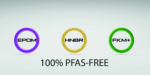
100% NO LEAKAGE, 100% PFAS-FREE
A complete range of weldless components dedicated to CO2 and A1-A2L-A3 gases, which use EPDM gaskets and HNBR, made with OLAB certified 100% PFAS-FREE elastomers. With excellent performance in terms of compression set and hardness.
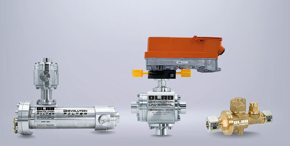
CO2 - R744
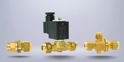
Extremely high performance, up to 150 bar/2175 psi guaranteed, zero welding, zero leakage. OLAB Ecosystem redefines professional refrigeration systems for R744 with the Ball Valve Specialist line, Series Revolution, and Fast Lock CO2, eliminating the problems of traditional solutions and optimizing energy, time, and costs. Solenoid valves, valves, and fittings of the highest quality and reliability, UL certified to meet the needs of international markets.
A1-A2L-A3 GASES
OLAB Ecosystem is synonymous with safety for professional refrigeration systems using flammable A1-A2L-A3 gases. The patented Fast Lock connection ensures perfect sealing without any welding; the ATEX certification of our coils guarantees the reliability of the solenoid valves 100% Made in OLAB.
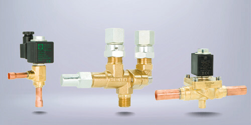
HFC
Our standard products for traditional refrigeration are not only versatile, but they also make no compromises in terms of safety, performance, and efficiency, thanks to a complete range of solenoid valves, valves, and fittings.