sistemi-di-refrigerazione-tradizionali

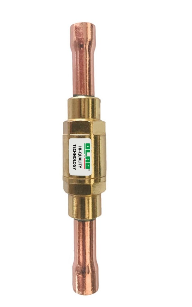
SERIES 33000

CHECK VALVES, REFRIGERANT FLUIDS HCFC-HFC-HFO-HC

SERIES 33000 CHECK VALVES, REFRIGERANT FLUIDS HCFC-HFC-HFO-HC

Category: TRADITIONAL REFRIGERATION SYSTEMS

Surface treatments applicable: no

Notes: 0

The check valves allow to avoid unwanted inversions of the direction of flow of the refrigerant inside the refrigeration system. They are characterized by a low differential opening pressure.

  • SOLID and SAFE
  • Guaranteed seal
  • Opening differential pressures from 0.1-0.3-1.5 bar 
  • 100% TESTED. Each valve is stamped with the date and serial number that certifies the passing of the test and allows traceability of the performance data recorded during the test over time.

The check valves are designed to be installed on refrigeration and air-conditioning systems for domestic and industrial use. It’s possible to use them with all the refrigerant fluids of group II (as defined in Article 13, chapter 1, Point b of Directive 2014/68/EU, with reference to EC Regulation No.1272/2008) and they are defined as “pressure equipments”, as described in Directive 2014/68/UE, Art.2 point 5 and Art.4 point 1.C.The check valves are designed to be installed on refrigeration and air-conditioning systems for domestic and industrial use. It’s possible to use them with all the refrigerant fluids of group II (as defined in Article 13, chapter 1, Point b of Directive 2014/68/EU, with reference to EC Regulation No.1272/2008) and they are defined as “pressure equipments”, as described in Directive 2014/68/UE, Art.2 point 5 and Art.4 point 1.C.The check valves are designed to be installed on refrigeration and air-conditioning systems for domestic and industrial use. It’s possible to use them with all the refrigerant fluids of group II (as defined in Article 13, chapter 1, Point b of Directive 2014/68/EU, with reference to EC Regulation No.1272/2008) and they are defined as “pressure equipments”, as described in Directive 2014/68/UE, Art.2 point 5 and Art.4 point 1.C.The check valves are designed to be installed on refrigeration and air-conditioning systems for domestic and industrial use. It’s possible to use them with all the refrigerant fluids of group II (as defined in Article 13, chapter 1, Point b of Directive 2014/68/EU, with reference to EC Regulation No.1272/2008) and they are defined as “pressure equipments”, as described in Directive 2014/68/UE, Art.2 point 5 and Art.4 point 1.C.

  • Brass body TN-UNI EN12164-CW614N (33000 series) or ST-UNI EN12165-CW617N (33100 series) 
  • Closing fitting made of brass TN-UNI EN12164-CW614N (33000 series)
  • Cover made of brass ST-NI EN12165-CW617N (33100 series)
  • Sealing O-ring made of Neoprene (HNBR option)
  • Stainless steel spring
  • Guide bush for brass gasket TN-UNI EN12164-CW614N
  • Sealing gasket made of PTFE
  • Brass pipe UNI-EN 12735/1 with ODF pocket
The main construction components of the check valves of the 33000-FM series are: 
  • Hot forged brass EN12164-CW614N for body and cover valves
  • Austenitic stainless steel AISI 3012 for the spring  HNBR + PTFE sealing gaskets

At the start-up of circuit is good to be sure that there are not dust or contamination inside the pipes. The arrow direction on body valve should be in accord with the flow direction inside the circuit. All mounting positions are accepted, even if is better to be in accord with the vertical axis. For 33100 series is accepted only the installation with orizontal axis. The braze welding of copper tubes should made by special alloy, with low melting point. The flame should not be directed toward the seals or body of valve, because it can damage the valve in consequence of overheating.At the start-up of circuit is good to be sure that there are not dust or contamination inside the pipes. The arrow direction on body valve should be in accord with the flow direction inside the circuit. All mounting positions are accepted, even if is better to be in accord with the vertical axis. For 33100 series is accepted only the installation with orizontal axis. The braze welding of copper tubes should made by special alloy, with low melting point. The flame should not be directed toward the seals or body of valve, because it can damage the valve in consequence of overheating.At the start-up of circuit is good to be sure that there are not dust or contamination inside the pipes. The arrow direction on body valve should be in accord with the flow direction inside the circuit. All mounting positions are accepted, even if is better to be in accord with the vertical axis. For 33100 series is accepted only the installation with orizontal axis. The braze welding of copper tubes should made by special alloy, with low melting point. The flame should not be directed toward the seals or body of valve, because it can damage the valve in consequence of overheating.At the start-up of circuit is good to be sure that there are not dust or contamination inside the pipes. The arrow direction on body valve should be in accord with the flow direction inside the circuit. All mounting positions are accepted, even if is better to be in accord with the vertical axis. For 33100 series is accepted only the installation with orizontal axis. The braze welding of copper tubes should made by special alloy, with low melting point. The flame should not be directed toward the seals or body of valve, because it can damage the valve in consequence of overheating.

models
33000-MM
33000-MM
close
33000-MM
33000-MM
33000-TS
33000-TS
close
33000-TS
33000-TS
33100-TS
33100-TS
close
33100-TS
33100-TS
33100-TNS
33100-TNS
close
33100-TNS
33100-TNS
33001.jpg
33001.jpg
close
33001.jpg
33001.jpg